VM1000 Videomatrix-System
Description
VM1000 is a modern video matrix system, amply provided with interfaces and various functions. It comprises of the following main components:
- VM1000 Videorack
- VM1000 CPU
This main components, together with the modules of the series make up the VM1000 Video Matrix System.
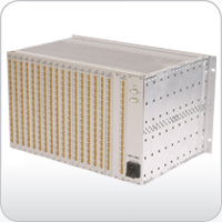
VM1000 Videorack
The video block is installed in a 6U rack according to IEC 60297 and can be equipped with up to 16 input cards and 2 output cards. This allows 512 inputs to be switched to 32 outputs. If loop-through inputs are required, 256 inputs to 32 outputs are available.
This video block can be controlled either via VM1000 CPU or PC video server. Up to 4 video blocks can be controlled, equalling 512 inputs to 128 outputs.
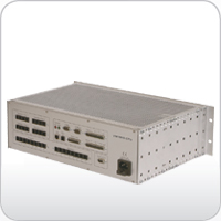
VM1000 CPU
The control processor of the VM1000 Video Matrix System is installed in a 3U rack according to IEC 60297. A detailed diagnostic report can be retrieved over a LAN connection using a web browser. In addition, a display shows the current status, and various diagnostic items can be called up using menu keys. Configuration settings or firmware updates can be conveniently uploaded over the LAN.
The VM1000 CPU is equipped with following interfaces:
- LAN connector connector for diagnostics and configuration
- SysControl output for connecting the VM1000 Video Rack
- SysLink interface for connecting up to 6 additional devices, e.g. alarm- or relay boxes
- 2 RS232 interfaces alternatively for controlling sub-devices, for configuring, or for controlling the system with a management system
- 1 RS232/RS422 interface (switchable) alternatively for controlling sub-devices, for configuring, or for controlling the system with a management system
- 4 dome camera telemetry connectors for connecting up to 4 dome cameras to each connector. All cameras connected to one connector must use the same control protocol (7 control protocols can be freely assigned via programming; additional control protocols are optionally available)
- 16 operating device connectors (6-pole modular jacks) Up to a line length of 50 m, all operating devices can be supplied with power by the VM1000 CPU power supply.
- 32 Alarm inputs
- 8 alarm outputs Open-Collector outputs for controlling signal lamps or relays
- 1 relay output with two galvanically isolated change-over contacts
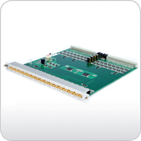
VM1000 VIDEO INPUT CARD 16
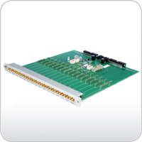
The VM1000 Video Input Card 16 has 16 loop-through inputs with 2 SMB connectors in parallel per input.
The video inputs hold 75 O terminating resistors that can be deactivated. Further functions are video signal detection for each input and DC video signal restauration.
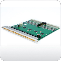
VM1000 VIDEO INPUT CARD 32
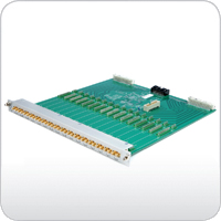
The VM1000 Video Input Card 32 has 32 video inputs with SMB connectors and 75 O terminators (non loop-through inputs).
The video inputs hold 75 O terminating resistors that can be deactivated. Further functions are video signal detection for each input and DC restauration of the video signal.
VM1000 OUTPUT CARD MASTER
The VM1000 Output Card Master provides 16 twin-outputs with SMB connectors. For each output in use, an SYS OSD Text Module must be plugged on.
VM1000 OUTPUT CARD SLAVE
The VM1000 Output Card Slave extends the VM1000 Output Card Master by 16 twin-outputs with SMB connectors. For each output in use, an SYS OSD Text Module must be plugged on.
SYS OSD TEXT MODULE
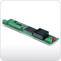
The SYS OSD Text Module holds the text generator and an output amplifier. Besides the standard ASCII character set, this module allows displaying of special characters. Each output of the VM1000 output card in use must be equipped with one SYS OSD Text Module.
Downloads
» Documentation, product software, etc.

